Clockwork uConsole · Volume 13
The Complete Build — NC-S Kit to Parrot on NVMe
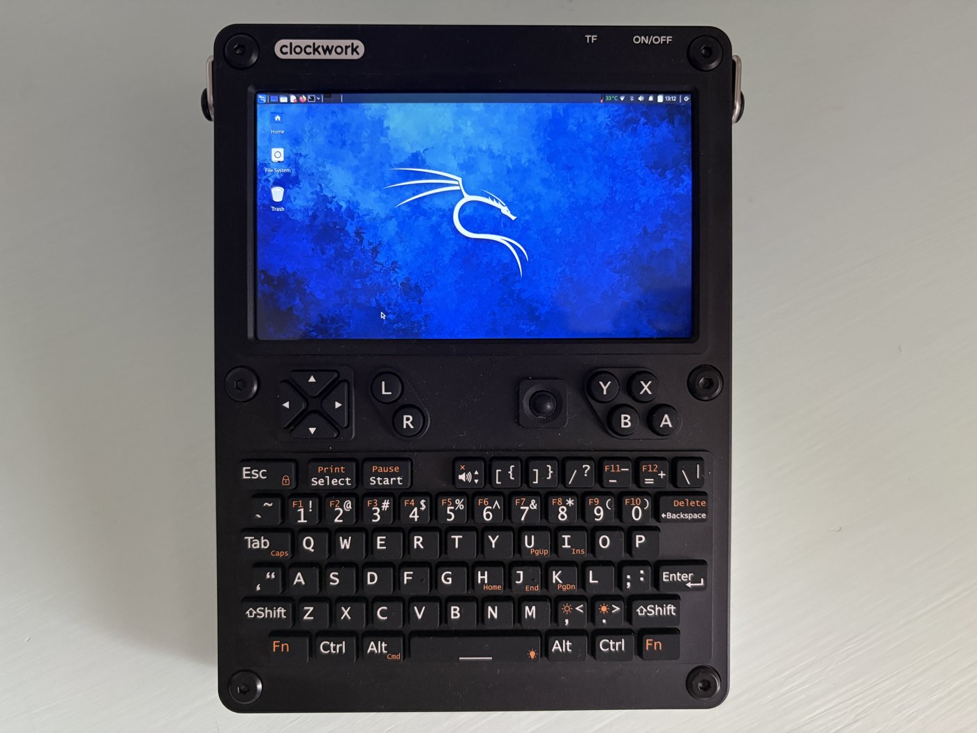
A step-by-step walkthrough: the bare uConsole NC-S NONE kit + HackerGadgets boards + Raspberry Pi CM5116032, assembled and booting ParrotOS from a 1 TB NVMe
This is the build volume. Where Vol 1 chooses a compute path, Vol 3 compares the modules, Vol 7 dissects the expansion boards at schematic depth, and the Full Loadout Manual V2 packs a three-case travel kit, this volume does one thing end to end: it takes a specific, named pile of parts and walks you — screw by screw, command by command — to a uConsole that powers on, boots ParrotOS from a 1 TB NVMe, and has every subsystem (display, keyboard, audio, Wi-Fi, Ethernet, USB 3.0, the SDR/LoRa/GPS radios, and the battery gauge) working correctly.
The exact build it documents is the one you asked for:
The uConsole NC-S NONE kit (bare — no compute module, no 4G), the HackerGadgets CM4/CM5 Adapter Board, the HackerGadgets NVMe Battery Board (no battery) with the correct lithium pack, the AIO V2 with RJ45 and USB 3.0, the 7-antenna extension board and antenna pack, a 1 TB NVMe, and a Raspberry Pi CM5116032 (the 16 GB-RAM, eMMC, wireless Compute Module 5).
A note on what this volume does not re-explain. Vol 7 already covers the HackerGadgets boards, the Mini-PCIe slot, IPEX seating, and the destructive ribbon hazard at engineer-grade depth, and the Parrot OS project carries a twelve-volume reference on the distribution itself (Wireshark, the tool inventory, AnonSurf internals). This volume cross-references both rather than duplicating them. What it adds — and what neither of those has — is the integrated, this-exact-BOM, boot-from-NVMe-on-a-CM5 sequence, including the two ways to actually get ParrotOS onto an ARM cyberdeck that has no official Parrot or CM5 image of its own.1
13.1 The Exact Build (Bill of Materials)
13.1.1 The shopping list
Table 1 — 2.1 The shopping list
| # | Component | Variant / spec to order | Source | Approx. USD |
|---|---|---|---|---|
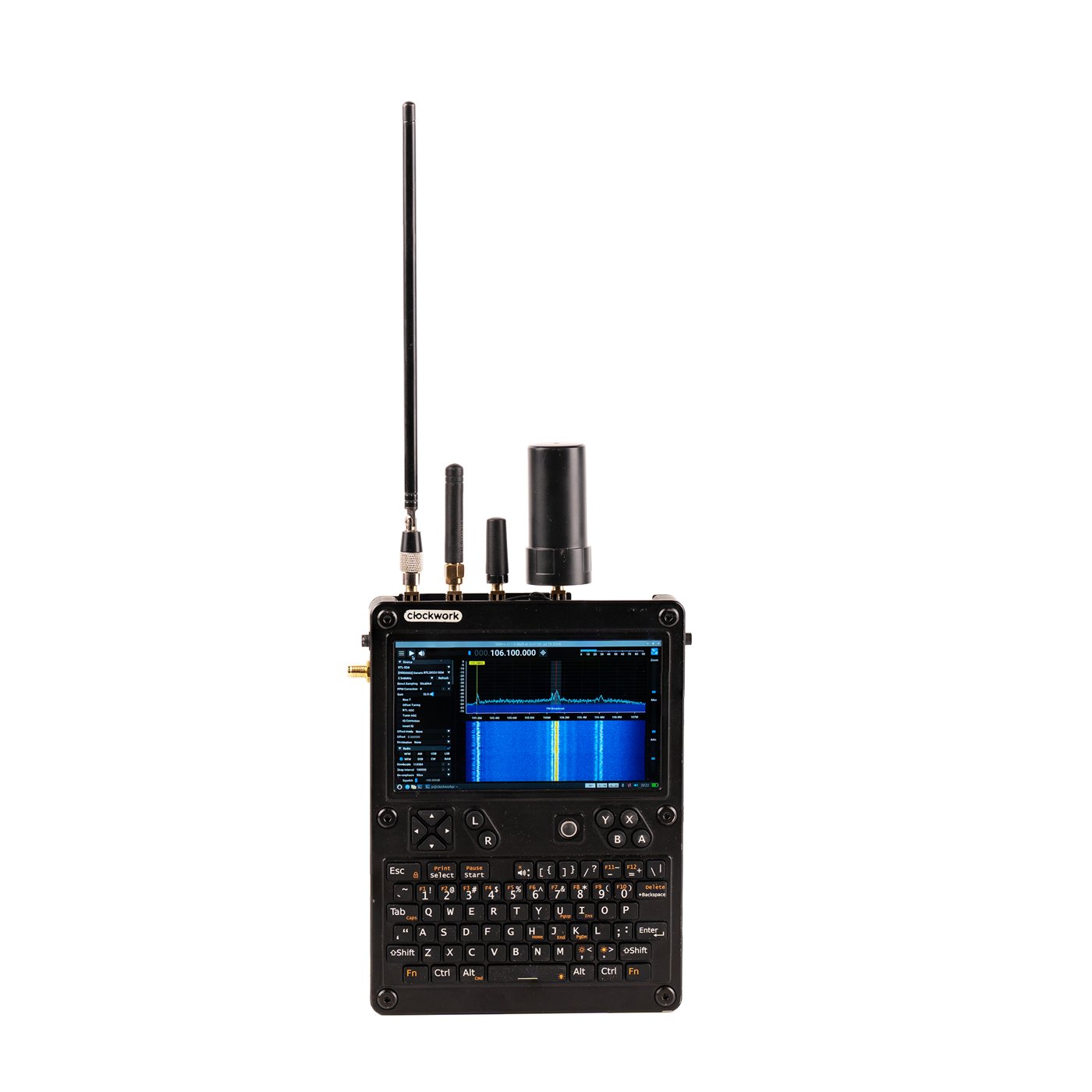
| 1 | uConsole kit — NC-S NONE | ”No Compute, No 4G” SKU. Bare kit: aluminium clamshell, V3.14_V5 mainboard, 5″ 1280×720 IPS, 74-key backlit keyboard, speakers, screen/keyboard ribbons, battery tray, screws. You supply the brain. | clockworkpi.com | ~$139 |
| 2 | Raspberry Pi CM5116032 | Compute Module 5, 16 GB LPDDR4X, 32 GB eMMC, wireless (Wi-Fi/BT). Broadcom BCM2712, quad Cortex-A76 @ 2.4 GHz. | PiShop / DigiKey / Mouser / Seeed | ~$135 |
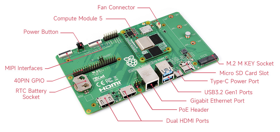
| 3 | HackerGadgets CM4/CM5 Adapter Board | From the “uConsole Upgrade Kit.” Exposes PCIe to the NVMe board, brings out USB 3.0 (CM5 only), PWM fan, RPITX, CSI2, RTC-battery, and the USB-C eMMC-flash port. | hackergadgets.com (Upgrade Kit) | (in kit, ~$23) |
| 4 | HackerGadgets NVMe Battery Board | From the same Upgrade Kit. M.2 M-key slot (2230 → 2280 all fit), accepts a single LiPo pack or two 18650s, reverse-polarity protection. | hackergadgets.com (Upgrade Kit) | (in kit) |
| 5 | AIO V2 — with RJ45 + USB 3.0 | All-In-One extension: RTL2832U+R860 SDR, SX1262 LoRa, GPS/GNSS, PCF85063A RTC, USB hub, USB 3.0, RJ45 1 Gbps. Ships in the 7-antenna configuration by default. | hackergadgets.com | ~$92 |
| 6 | 7-antenna mounting kit + antenna pack | The 7-mount bracket (default-ship with AIO V2) plus the seven tuned SMA/IPEX antennas. | hackergadgets.com | ~$35 (pack) |
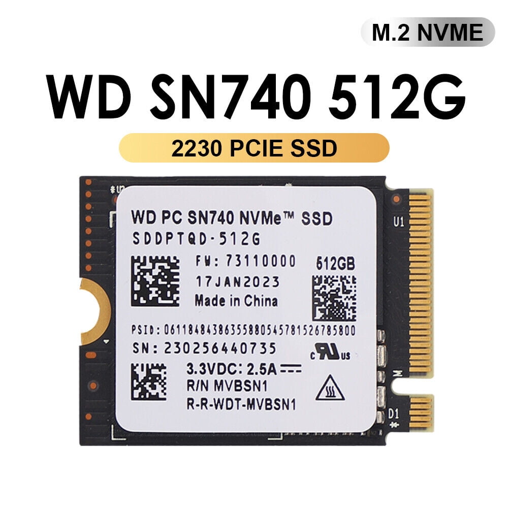
| 7 | 1 TB NVMe SSD | WD SN740 1 TB, M.2 2230 recommended (see §2.4). | OEM resellers / Amazon | ~$80–110 |
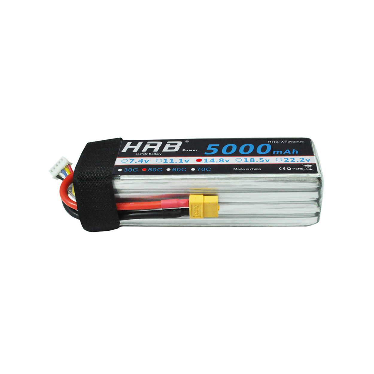
| 8 | LiPo flat pack — 9858110, 5000 mAh | Single-cell 3.7 V, ~18.5 Wh, with integrated PCB protection and a JST connector matching the NVMe Battery Board (see §2.5). | hackergadgets.com or LiPo vendor | ~$25 |
The “NONE / NC-S” SKU is simply ClockworkPi’s name for the kit with No Compute module and no cellular — it is the right kit to buy when you are bringing your own CM5, exactly as here.
13.1.2 A spec correction up front — CM5116032 is 16 GB / 32 GB
You described the module as “16 GB/16 GB.” There is no such SKU. Raspberry Pi’s part numbering is CM5 · 1 (wireless) · 16 (GB RAM) · 032 (GB eMMC):2
- CM5116032 = 16 GB RAM / 32 GB eMMC / wireless — the part you named, and the right one.
- (
CM5016032is the same RAM/eMMC but without wireless; you do not want that one.)
So you are getting more flash than you expected — 32 GB of eMMC, not 16 GB. That is a happy accident: this build uses the eMMC as the recovery device (§7.2), and 32 GB is comfortably enough for a full stock Clockwork image plus headroom. The whole volume is written against the correct 16 GB / 32 GB / wireless spec.
13.1.3 Why this exact set fits together (and what it replaces)
The HackerGadgets “uConsole Upgrade Kit” ships three boards: the Adapter Board, the NVMe Battery Board, and a small RJ45 + USB 3.0 expansion board.3 Your list takes the first two and then uses the AIO V2 instead of that third little board — and that is exactly right, because the AIO V2 already provides RJ45 and USB 3.0 (on top of the SDR/LoRa/GPS/RTC/USB-hub).4 You would be double-buying the Ethernet port if you installed both. So the intended interpretation of your BOM is:
- Adapter Board + NVMe Battery Board — taken from the Upgrade Kit.
- AIO V2 — the expansion board, providing RJ45 + USB 3.0 + radios.
- The Upgrade Kit’s third (RJ45/USB-3-only) board — unused, set aside as a spare.
One dependency to internalise: the AIO V2’s RJ45 port only works with the new Adapter Board installed — the gigabit MAC is routed through the adapter, not the stock mainboard.4 Since this build uses that adapter anyway, you are covered. Likewise USB 3.0 is a CM5-only feature — on a CM4 those ports fall back to USB 2.0.3 You have a CM5, so you get the real thing.
13.1.4 The 1 TB NVMe — vendor and spec recommendation
The NVMe Battery Board takes M.2 M-key sizes 2230 through 2280.3 All three lengths physically fit, so the only real decisions are thermals, power, and how much the slot can actually use.
The slot is the bottleneck, not the drive. The CM5 exposes a single PCIe lane, default Gen 2 ×1 (~450 MB/s practical), forceable to Gen 3 ×1 (~800 MB/s) on the uConsole adapter where signal integrity allows.5 A headline “7000 MB/s Gen 4 ×4” drive is capped to that single lane here — you are paying for numbers you cannot reach. Buy for efficiency and heat, not peak bandwidth.
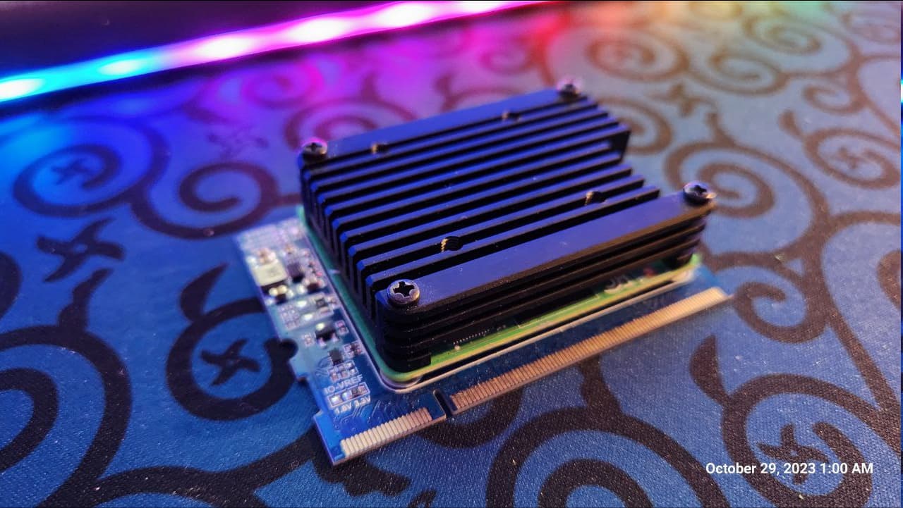
Recommended: WD SN740 1 TB, M.2 2230. It is the OEM drive Steam Deck and other handhelds ship — designed for exactly this thermal/power envelope, single-sided, runs cool, and the 2230 length leaves the most clearance for the LiPo and the AIO V2 above it.
Table 2 — 2.4 The 1 TB NVMe — vendor and spec recommendation
| Model | Length | Rated R/W | Notes |
|---|---|---|---|
| WD SN740 1 TB (pick) | 2230 | 5150 / 4900 MB/s | OEM handheld drive; coolest, single-sided, native fit |
| Sabrent Rocket 2230 1 TB | 2230 | 5000 / 3700 MB/s | Good retail availability in 2230 |
| Inland TN436 / generic 2242 1 TB | 2242 | 4500 / 3500 MB/s | Budget; fits with the 2242 standoff |
| Crucial P3 Plus 1 TB | 2280 | 5000 / 3600 MB/s | Cheapest $/GB, but 2280 eats clearance |
| Samsung 990 EVO 1 TB | 2280 | 5000 / 4200 MB/s | Premium, cooler 2280 option |
For this build, the WD SN740 2230 is the recommendation. If you already own a 2280 drive, it works — just confirm the LiPo and AIO V2 still seat without strain (§3.4).
13.1.5 The matching lithium pack for the NVMe Battery Board
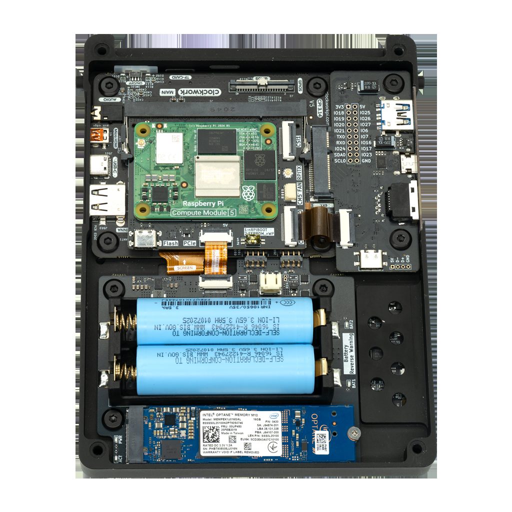
The NVMe Battery Board accepts either two 18650 cells or a single LiPo flat pack.3 For this build the LiPo is the right call: it lays flat alongside the NVMe without fighting the AIO V2 for space, and a single cell sidesteps the 18650 pair-mismatch problem (Vol 11 §4.1).
The correct pack: a 9858110 LiPo, single-cell, 3.7 V nominal, 5000 mAh (~18.5 Wh), with an integrated protection PCB and a JST-PH connector. The number is the dimensions — 98 × 58 × 11.0 mm — which is the size the battery bay is cut for.6
Table 3 — 2.5 The matching lithium pack for the NVMe Battery Board
| Pack | Energy | Rough runtime (light load) | Fit |
|---|---|---|---|
| 9858110, 4000 mAh | ~14.8 Wh | ~5 h | Easy |
| 9858110, 5000 mAh (pick) | ~18.5 Wh | ~6–6.5 h | Sweet spot |
| 9858110, 6000 mAh | ~22.2 Wh | ~8 h | Only some bays |
Sizing the pack for a CM5 running flat-out is a real concern, not a formality. A single cell feeding a 15–18 W CM5+SDR load through the 5 V boost must source ~5 A — at which point the pack’s continuous-discharge rating and its protection-board trip point decide whether the device stays on, and many packs (and most spec-less marketplace listings) can’t sustain it. The shorter 9858102 (98 × 58 × 10.2 mm) is the same family chosen to leave room to stack two in parallel, which doubles runtime and halves the per-pack current. The full power-budget math, how to read a pack’s real limits, the parallel-stacking rules, charge/discharge rates, and the USB-C input ceiling are in Vol 11 §4.7–§4.11.
The NVMe Battery Board has reverse-polarity protection with a warning LED — but do not rely on it. Confirm connector polarity against the board silkscreen before plugging the pack in.3 LiPo safety is non-optional: never charge below 0 °C or above 45 °C; never puncture or crush; if the pack ever swells, retire it immediately to a battery-recycling drop-off. At 18.5 Wh the pack is far under the 100 Wh airline carry-on limit.
13.1.6 Tools and consumables you also need
- A host computer (Linux easiest; Windows/macOS work) running Raspberry Pi Imager and the
rpiboot/usbboottool — used to flash the eMMC and to fix the EEPROM (§4). - A USB-C cable (data-capable) for the Adapter Board’s eMMC-flash port.
- A USB → M.2 NVMe enclosure (USB 3.x, supports 2230/2242) to pre-flash the SSD on the bench (§5.2). ~$15.
- A Phillips PH00 screwdriver, a plastic spudger/pry tool, and an IPEX/U.FL seating tool (or a clean fingernail).
- A CR1220 coin cell for the AIO V2’s RTC.4
- Thermal pad or a 1 mm copper shim + a 25 mm 5 V PWM fan (the Adapter Board has a PWM fan header — variable-speed on CM5).3 The CM5 runs warm under sustained load; budget for cooling (Vol 11 §2).
- The longer screws HackerGadgets ships with the AIO V2 — the board stack is taller than stock and the kit screws are needed (Vol 7 §11.2).
- Optional but recommended: a TEAMGROUP A2 Pro Plus 128 GB microSD as a known-good card if you ever need to fall back to SD-booting a Lite module on the bench. (On this build the eMMC disables the SD slot — see §3.2 — so it is a bench tool, not part of the final device.)7
13.1.7 Cost roll-up
Table 4 — 2.7 Cost roll-up
| Block | USD |
|---|---|
| uConsole NC-S NONE kit | ~$139 |
| CM5116032 (16/32/wireless) | ~$135 |
| HackerGadgets Upgrade Kit (Adapter + NVMe + spare RJ45 board) | ~$23 |
| AIO V2 (RJ45 + USB 3.0) | ~$92 |
| 7-antenna pack | ~$35 |
| WD SN740 1 TB 2230 | ~$95 |
| 9858110 5000 mAh LiPo | ~$25 |
| Consumables (enclosure, CR1220, fan/shim, microSD) | ~$45 |
| Total | ~$589 |
A complete, 16 GB, NVMe-booting, gigabit-Ethernet, SDR-equipped Linux cyberdeck for under $600 — and most of that is the CM5 and the AIO V2.
13.2 How the Boards Stack — Compatibility & Sequencing
13.2.1 The signal map: PCIe, USB 3.0, Ethernet
Three buses leave the CM5 through the Adapter Board, and it is worth knowing where each goes before you assemble:
- PCIe Gen 2 ×1 → the NVMe Battery Board (your boot drive). Vol 7 §6 has the lane-routing detail.
- USB 3.0 (CM5 only) → brought out by the Adapter Board and consumed by the AIO V2’s USB hub and Type-A/Type-C ports.34
- Gigabit Ethernet MAC → routed through the Adapter Board to the AIO V2’s RJ45 jack.4
The practical consequence: the Adapter Board is load-bearing for the whole build. NVMe boot, USB 3.0, and RJ45 all depend on it. Install it first and seat it well.
13.2.2 The eMMC-and-SD-share-a-bus rule (why the microSD slot is dead)
This is the single most important architectural fact for a CM5-with-eMMC build, and it shapes the whole boot design:
On the CM5, the eMMC and the microSD slot are on the same bus. If the module has eMMC populated, the SD card slot does not work.8
Your CM5116032 has 32 GB of eMMC. Therefore the uConsole’s microSD slot is non-functional in this build. That is not a defect — it is how the silicon multiplexes. It is also why this volume puts the recovery image on the eMMC instead of on an SD card (§7.2): the eMMC is the only on-module storage you can boot, and it is the natural fallback when the NVMe is the daily driver. (A Lite CM5 with no eMMC would behave the opposite way — SD becomes the recovery device — but that is a different build.)
13.2.3 The NVMe power-draw trade-off — read this before you commit
Honesty up front: an NVMe SSD draws noticeably more power than the CM5’s onboard eMMC, and it will cut your battery runtime. Experienced uConsole builders are blunt about it — an eMMC CM5 gives “great stability, low power, optimal speeds,” while NVMe trades some of that runtime for capacity and sequential throughput.9
You are booting from NVMe deliberately, and for good reasons — 1 TB of fast storage for VMs, wordlists, captures, and a full Parrot install is the whole point. Just go in clear-eyed:
- Expect roughly 1–1.5 h less runtime than an eMMC-only build on the same pack.
- Power-gate what you are not using. The AIO V2’s SDR/LoRa/GPS/internal-USB rails are GPIO-controlled and default OFF — leave them off until needed (§11.6).4
- A low-power 2230 drive (the WD SN740 pick) minimises the penalty.
- If runtime ever matters more than capacity for a given trip, the eMMC recovery image is a genuinely usable low-power fallback (§7.3).
13.2.4 Physical stack-up and clearance
The HackerGadgets boards make the back of the uConsole taller than stock. Two consequences:
- Use the longer screws from the AIO V2 kit; the stock screws will not reach the threads with the full stack installed (Vol 7 §11.2).
- Mind the LiPo + NVMe + AIO V2 sandwich. A 2230 SSD and the flat LiPo coexist cleanly. A 2280 SSD eats into the space the LiPo wants — if you insist on 2280, test-fit before final assembly and accept you may give up the larger pack.
13.3 Pre-Build: Prepare the CM5 (EEPROM & Bootloader)
13.3.1 Why the EEPROM comes first
The CM5’s bootloader lives in an on-module EEPROM, and out of the box it does not know to boot from NVMe — and older firmware is fussy about storage altogether. You must update and configure it before the module is buried inside the case. Doing it on the bench, over the Adapter Board’s USB-C flash port, is far easier than doing it after assembly.
- The CM5 must be running bootloader firmware dated after 2025-01-06. Earlier firmware predates reliable NVMe boot on these adapters.
- The EEPROM
BOOT_ORDERmust include NVMe, and a couple of CM5 timing quirks must be set.
13.3.2 Bench rig: rpiboot from a host PC
You will talk to the CM5 as a USB device using Raspberry Pi’s usbboot/rpiboot tool. On a Linux host:
git clone --recurse-submodules --shallow-submodules --depth=1 \
  https://github.com/raspberrypi/usbboot
cd usbboot && make
sudo make install        # provides rpiboot
Mount the CM5 on the Adapter Board, set the Adapter’s flash jumper to the flash position (the two switches “both to the right”), and connect the Adapter’s USB-C flash port to the host.9 The CM5 now enumerates as a device rpiboot can drive.
13.3.3 Update the bootloader firmware (post-2025-01-06)
The cleanest way to both update and configure the EEPROM is to do it from a running OS once — but at this stage the module is bare, so use the usbboot recovery flow, which writes a fresh, current bootloader directly:
cd usbboot/recovery5     # NOTE: recovery5 — the CM5 directory, not 'recovery'
./update-pieeprom.sh     # builds pieeprom.bin from the latest firmware + boot.conf
cd ..
sudo rpiboot -d recovery5
recovery5 (not recovery) is essential — it carries the CM5-specific bootloader.8 After rpiboot reports success, power-cycle. The CM5 now has current firmware.
If you prefer to verify from software later: once any OS is booted you can run
vcgencmd versionto read the firmware date andsudo rpi-eeprom-updateto confirm you are current.7
13.3.4 The EEPROM config — exact lines, with BOOT_ORDER explained
Edit boot.conf inside recovery5 before running update-pieeprom.sh (or, from a booted OS, sudo rpi-eeprom-config -e). The community-standard uConsole CM5 config is:78
[all]
BOOT_UART=1
POWER_OFF_ON_HALT=1
BOOT_ORDER=0xf461
SD_BOOT_MAX_RETRIES=2
SD_QUIRKS=1
What each line does:
BOOT_UART=1— serial debug output, so a UART console can see early boot. Harmless to leave on.POWER_OFF_ON_HALT=1— actually powers down the PMIC onhaltinstead of idling (saves battery, matters on a handheld).SD_BOOT_MAX_RETRIES=2andSD_QUIRKS=1— slow and retry the SD/eMMC interface during the bootloader phase, working around CM5 timing sensitivity.7BOOT_ORDER=0xf461— the boot search order. Read the hex right-to-left, one device per nibble:10
Table 5 — 4.4 The EEPROM config — exact lines, with BOOTORDER explained
| Nibble (R→L) | Value | Device |
|---|---|---|
| 1st | 1 | SD / eMMC (on a CM with eMMC populated, 1 is the eMMC) |
| 2nd | 6 | NVMe |
| 3rd | 4 | USB mass storage |
| 4th | f | restart the sequence (loop) |
So 0xf461 means eMMC → NVMe → USB → loop. That is the community default, and it boots the eMMC first.
13.3.5 Choosing the boot order for this build (NVMe daily, eMMC recovery)
The default 0xf461 boots eMMC-first — the opposite of what you want. This build runs Parrot on the NVMe as the daily OS, with the eMMC holding a stock recovery image as a fallback (§7.2). So flip the first two nibbles:
BOOT_ORDER=0xf416Table 6 — 4.5 Choosing the boot order for this build (NVMe daily, eMMC recovery)
| Nibble (R→L) | Value | Device |
|---|---|---|
| 1st | 6 | NVMe (Parrot — daily) |
| 2nd | 1 | eMMC (stock recovery — automatic fallback) |
| 3rd | 4 | USB mass storage |
| 4th | f | restart the sequence (loop) |
0xf416 = NVMe → eMMC → USB → loop. Normal power-on lands in Parrot. If the NVMe is ever missing, unflashed, or unbootable, the bootloader falls through to the stock eMMC image automatically. Keep every other line identical:
[all]
BOOT_UART=1
POWER_OFF_ON_HALT=1
BOOT_ORDER=0xf416
SD_BOOT_MAX_RETRIES=2
SD_QUIRKS=1
For a deliberate recovery boot while the NVMe is perfectly healthy, see the uconsole-bootsel helper in §7.3.
13.4 Pre-Build: Pre-Flash the NVMe and the eMMC
13.4.1 Why pre-flash on the bench
You can assemble first and flash later, but pre-flashing the NVMe in a USB enclosure and writing the eMMC over the Adapter’s flash port — both while everything is still accessible — means first power-on is a confidence check, not a debugging session. Do it now.
13.4.2 Pre-flash the NVMe over USB
Put the WD SN740 in the USB→M.2 enclosure and connect it to your host. Identify it carefully (lsblk), then write your chosen Parrot image to it. The two image choices are detailed in §8–§10; the mechanics are the same either way:
lsblk                                  # find the enclosure, e.g. /dev/sda — be SURE
xz -dc <image>.img.xz | sudo dd of=/dev/sdX bs=4M status=progress conv=fsync
sync
Replace /dev/sdX with the enclosure’s device node — never your host disk. Raspberry Pi Imager works too; if you use it, do not apply the customisation (gear-icon) settings — on the Clockwork images those break first boot.8
Set the NVMe aside (still in the enclosure is fine) until §9/§10, where you finish OS setup.
13.4.3 Write the stock recovery image to the CM5 eMMC
With the CM5 on the Adapter Board, the flash jumper in flash position, and the USB-C flash port connected to the host, expose the eMMC as a block device:
sudo rpiboot              # CM5 eMMC now appears as e.g. /dev/sdX
lsblk
Then write a known-good stock image as the recovery fallback. Use Rex’s ClockworkPi-Bookworm-6.12.y image (the community standard, kernel 6.12, with the Clockwork patches built in) — it is the most reliable “always boots, screen and keyboard just work” image to keep in your back pocket:11
xz -dc ClockworkPi-Bookworm-6.12.45.img.xz | sudo dd of=/dev/sdX bs=4M status=progress conv=fsync
sync
Return the flash jumper to the normal (run) position when done.9 The eMMC now holds a self-contained recovery OS; the NVMe holds (or will hold) Parrot.
13.5 Hardware Assembly — Five Phases
Vol 7 is the schematic-grade reference for these boards; this section is the ordered, do-this-then-that build. Work on an anti-static surface. Do not connect the charger or power on at any point during assembly — only after the ribbon-orientation check in §6.6.
13.5.1 Phase 1 — CM5 onto the Adapter Board, Adapter onto the mainboard
- Open the NC-S kit. Remove the back panel and locate the 200-pin Compute-Module connector on the mainboard.
- Seat the CM5116032 onto the Adapter Board’s module connector — align the two board-to-board connectors and press evenly until they click flat. The CM5 should sit parallel, no gap.
- Fit the CR1220 into the Adapter/AIO RTC holder (§6.3 covers which holder on your AIO V2 revision).9
- If you are fitting the copper shim/thermal pad, place it on the CM5’s SoC now, and connect the PWM fan to the Adapter’s fan header (variable-speed on CM5).
- Seat the Adapter Board (with CM5 attached) onto the mainboard’s module connector. Press evenly; confirm it is flat and fully home.
13.5.2 Phase 2 — NVMe Battery Board: SSD + LiPo
- Install the WD SN740 2230 into the NVMe Battery Board’s M.2 slot at ~30°, then press flat and secure with the 2230 standoff screw.
- Connect the 9858110 LiPo to the board’s battery connector — check polarity against the silkscreen first (§2.5). The reverse-polarity LED is a safety net, not a license to guess.3
- Mount the NVMe Battery Board per the kit’s standoffs and connect it to the Adapter Board’s PCIe connector. Route the LiPo flat in its bay; do not pinch it under a standoff.
13.5.3 Phase 3 — AIO V2 (RJ45 / USB 3.0 / SDR / LoRa / GPS)
- Confirm the AIO V2’s CR1220 RTC cell is seated (holder location varies by revision — on V2 it is on the AIO card itself).9
- Mount the AIO V2 above the NVMe board on the kit standoffs. Connect its USB 3.0 internal header/Type-C to the Adapter Board’s USB 3.0 source, and confirm the RJ45 path runs through the Adapter (the gigabit MAC needs it).4
- Leave the SDR/LoRa/GPS rails as-is — they are GPIO-gated OFF by default and you will enable them in software (§11.6).4
13.5.4 Phase 4 — The 7-antenna board and antenna pack
The 7-antenna bracket mounts to the back panel and breaks out seven IPEX/U.FL feedthroughs to external SMA antennas. A sane allocation for this loadout:
Table 7 — The 7-antenna bracket mounts to the back panel and breaks out seven IPEX/U.FL feedthroughs to external SMA antennas. A sane allocation for this loadout
| Mount | Antenna | Feeds |
|---|---|---|
| 1 | Broadband whip (50 MHz–1.7 GHz) | AIO V2 RTL-SDR (RTL2832U+R860)4 |
| 2 | 915 MHz (US) / 868 MHz (EU) | AIO V2 LoRa (SX1262) |
| 3 | Active GPS (1.575 GHz) | AIO V2 GPS/GNSS |
| 4 | Wi-Fi 2.4 GHz | CM5 onboard radio (ant2) |
| 5 | Wi-Fi 5 GHz | CM5 onboard radio (second feed) |
| 6 | Spare / second LoRa or Meshtastic | — |
| 7 | Spare / cellular (if an LTE card is ever added) | — |
Seat each IPEX connector until it clicks — press straight down with a flat tool, never pull the coax. A partly-seated U.FL is the usual cause of “the SDR is deaf” (Vol 7 §11.4). Cap unused mounts with the plastic stubs so the case still closes.
13.5.5 Phase 5 — Ribbons, cooling, close-up
- Reconnect the display and keyboard ribbons to the mainboard. (See §6.6 — this is the dangerous step.)
- Confirm the fan lead is on the Adapter’s PWM header and the fan spins freely.
- Tidy the LiPo and antenna pigtails so nothing is pinched by the back panel.
- Fit the back panel with the longer AIO V2 screws (Vol 7 §11.2). Do not force stock screws into too-short engagement.
13.5.6 The destructive ribbon-orientation hazard (do not skip)
A ribbon cable inserted 180° backwards will destroy the mainboard the instant you connect the charger. This is the single most expensive mistake on a uConsole build, and HackerGadgets calls it out explicitly: “Never ever plug in the charger if the ribbon cable is installed the wrong way; otherwise, it will damage the uConsole mainboard.”3
Before any power touches the device:
- Re-seat each ribbon and verify the coloured stripe / pin-1 indicator matches the silkscreen on both ends.
- Confirm the contacts face the correct side and the latch is closed.
- Only after both ribbons are verified do you connect the LiPo and, separately, the charger.
If you have already applied power with a reversed ribbon, assume mainboard damage and see Vol 7 §5.3. Prevention is the only cure.
13.6 First Power-On and the Boot Architecture
13.6.1 The pre-OS sanity check
With ribbons verified, LiPo connected, and the NVMe + eMMC both pre-flashed:
- Press power. You should see the bootloader hand off and an OS begin to load from the NVMe (Parrot). If the screen is black on this first cold boot, that is the known CM5 panel cold-boot quirk, not a build failure — see §11.1.
- Once up, confirm both storage devices are present:
lsblk
# expect: nvme0n1 (~1 TB, your Parrot rootfs) AND mmcblk0 (~32 GB eMMC recovery)- Confirm you actually booted from the NVMe:
findmnt / # SOURCE should be /dev/nvme0n1p2 (or similar), not mmcblk0If / is on nvme0n1, the core goal — booting from the NVMe — is met. The rest of the volume makes it work perfectly.
13.6.2 The boot architecture for this build
   power on
      │
      ▼
  CM5 bootloader  (BOOT_ORDER = 0xf416)
      │
      ├─ 6: NVMe present & bootable? ──► YES ──► ParrotOS  (daily driver)
      │                                  NO
      ├─ 1: eMMC stock image ───────────────► Clockwork Bookworm (recovery)
      │                                  (auto-fallback)
└─ 4: USB mass storage ───────────────► bench rescue- NVMe = ParrotOS, your daily OS, the thing you actually use.
- eMMC (32 GB) = stock Clockwork Bookworm 6.12, a known-good recovery OS that always brings up the screen and keyboard — invaluable when you have broken something in Parrot and need a working shell to fix it.
- The fallback is automatic (NVMe unbootable → eMMC). For a deliberate recovery boot, use the helper below.
13.6.3 A selectable recovery: the uconsole-bootsel helper
The Raspberry Pi bootloader has no interactive boot-picker, but you do not need one — a tiny script that rewrites BOOT_ORDER and reboots gives you a clean, deliberate selector. Install this on the eMMC recovery image (and, if you like, on Parrot too):
sudo tee /usr/local/sbin/uconsole-bootsel >/dev/null <<'EOF'
#!/usr/bin/env bash
# uconsole-bootsel nvme|emmc  — choose the next boot device and reboot.
set -euo pipefail
case "${1:-}" in
  nvme) ORDER=0xf416 ;;   # NVMe first, eMMC fallback  (daily)
  emmc) ORDER=0xf461 ;;   # eMMC first, NVMe fallback  (recovery)
  *) echo "usage: uconsole-bootsel nvme|emmc" >&2; exit 1 ;;
esac
TMP=$(mktemp)
sudo rpi-eeprom-config > "$TMP"
sed -i "s/^BOOT_ORDER=.*/BOOT_ORDER=$ORDER/" "$TMP"
sudo rpi-eeprom-config --apply "$TMP"
echo "BOOT_ORDER set to $ORDER; rebooting…"
sudo reboot
EOF
sudo chmod +x /usr/local/sbin/uconsole-bootsel
Usage:
sudo uconsole-bootsel emmc   # from Parrot: drop into the eMMC recovery OS
sudo uconsole-bootsel nvme   # from recovery: go back to Parrot on NVMe
It just edits the one config line and reboots, so it is safe and reversible. (Under the hood it uses rpi-eeprom-config --apply, which re-flashes the EEPROM with your edited config.7)
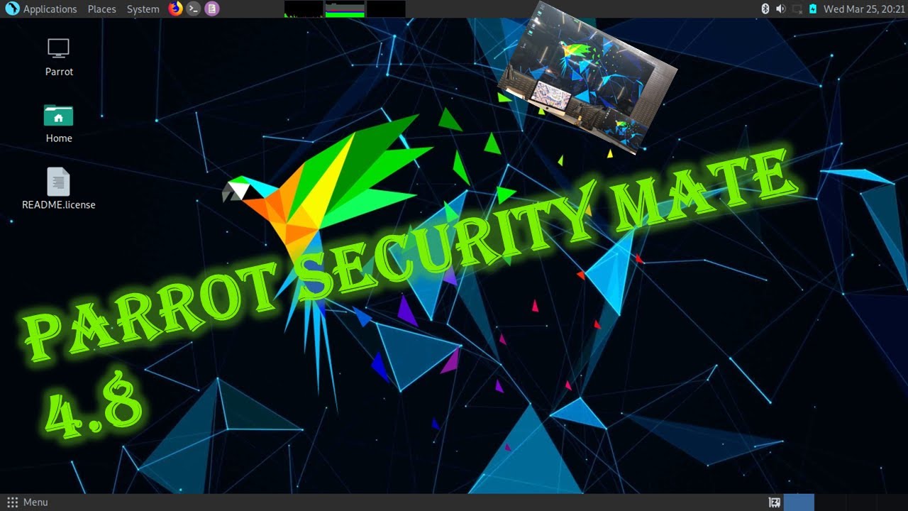
13.7 Installing Parrot — Two Co-Equal Paths
Here is the crux, and the reason the OS half of this volume needs care: ParrotOS publishes no uConsole image, and ClockworkPi publishes no CM5 image. The official Clockwork repo ships CM4/A06/R01 images only, and Parrot’s ARM images target stock Raspberry Pi boards, not the uConsole’s panel and keyboard.112 Getting ParrotOS onto this device therefore always means combining Parrot’s userland with Rex’s community Clockwork CM5 kernel/patches. There are two clean ways to do that, and this volume documents both at equal depth so you can pick.
13.7.1 Which path should you take?
Table 8 — 8.1 Which path should you take?
| Path 1 — Patched base + Parrot layer | Path 2 — Upstream Parrot + grafted support | |
|---|---|---|
| Start from | Rex’s Clockwork Bookworm 6.12 image (screen/keyboard already work) | Official ParrotOS RPi arm64 image |
| You add | The Parrot archive + parrot-tools + AnonSurf | Rex’s kernel + device-tree overlay + audio/Wi-Fi fixes |
| ”It’s really Parrot?” | Parrot tools on a Debian/Clockwork base | Genuine ParrotOS userland, top to bottom |
| Risk of a hardware quirk | Low — the base is known-good | Medium — you are porting Clockwork support |
| Best for | ”I want it working perfectly, fast" | "I want true ParrotOS and don’t mind tinkering” |
Both end at the same place — ParrotOS tools, AnonSurf, the Parrot menu, booting from your NVMe with every peripheral alive. If you want the highest chance of “works perfectly” on the first try, take Path 1. If you specifically want the genuine Parrot base system, take Path 2. You can even keep one on the NVMe and the other on the eMMC.
A third option exists if you would rather not build at all: vendors such as Carbon Computers sell the uConsole CM5 pre-imaged with ParrotOS as a checkout choice — useful as a reference image to clone, though you lose the learning (and the NVMe-boot tuning) this volume gives you.13
13.8 Path 1 — Patched Base + Parrot Layer (most reliable)
The idea: start from an image where the uConsole hardware already works, then add Parrot’s security userland on top. Because both Parrot’s RPi images and Rex’s image are Debian-Bookworm-based, the Parrot tools drop in cleanly via Parrot’s own apt archive.
13.8.1 Flash Rex’s Bookworm 6.12 image to the NVMe
You already wrote this image to the eMMC as the recovery OS (§5.3); now write the same image to the NVMe, which will become your Parrot daily driver:
# NVMe in the USB enclosure on your host:
xz -dc ClockworkPi-Bookworm-6.12.45.img.xz | sudo dd of=/dev/sdX bs=4M status=progress conv=fsync
sync
Download it from Rex’s distribution links (Mega / Google Drive / Drime) referenced from the forum thread; 6.12.45 is the build that enabled PCIe and Ethernet for the new HackerGadgets adapter boards — use that or newer.11
13.8.2 First boot, verify the Clockwork hardware
Install the NVMe in the device (or, if assembled, it is already there), power on, and confirm the base is healthy before layering anything:
findmnt /                      # should be on /dev/nvme0n1p*
uname -r                       # 6.12.x
nmcli dev wifi list            # Wi-Fi radio alive
ip link                        # eth0 present (RJ45 via AIO V2)
Expand the root filesystem to fill the 1 TB if the image did not auto-grow:
sudo raspi-config # Advanced → Expand Filesystem, then rebootKeep Rex’s kernel and firmware on their existing apt channel so security/hardware updates keep flowing:8
sudo apt update && sudo apt full-upgrade -y13.8.3 Add the Parrot archive and pull parrot-tools
Parrot’s tools install on any Debian system from Parrot’s own archive. Add it, then pull the metapackage set:14
# 1) Parrot archive keyring + sources (Bookworm-compatible 'lory'/rolling line)
sudo apt install -y curl ca-certificates gnupg
curl -fsSL https://deb.parrot.sh/parrot/pool/main/p/parrot-archive-keyring/ \
  -o /tmp/keyring.info   # follow the keyring package link for the current .deb
# Install the parrot-archive-keyring .deb you fetched, then:
echo "deb https://deb.parrot.sh/parrot lory main contrib non-free non-free-firmware" \
  | sudo tee /etc/apt/sources.list.d/parrot.list
sudo apt update

# 2) Pin so the Clockwork kernel/firmware stay from Rex, tools come from Parrot
sudo tee /etc/apt/preferences.d/parrot-tools <<'EOF'
Package: *
Pin: release o=Parrot
Pin-Priority: 100

Package: parrot-* anonsurf
Pin: release o=Parrot
Pin-Priority: 500
EOF
sudo apt update
Why the pin matters. Without it, Parrot’s archive could try to replace Rex’s
clockworkpi-kernel/firmware with stock packages and break the display. The pin keeps the base + kernel on Rex’s channel and only lets Parrot tool packages (and AnonSurf) install from Parrot. Verify after each big change thatapt-cache policy clockworkpi-kernelstill points at Rex’s repo.8
Now choose your tool depth:
sudo apt install -y parrot-tools-common      # base security toolset, lighter
# or, for the full Kali-parity arsenal (large — mind the storage budget):
sudo apt install -y parrot-tools-full
parrot-tools-full is what gives you “everything Parrot ships” — Nmap, Wireshark, Aircrack-ng, Metasploit, Burp, the works — and on 1 TB you have room for it.14 The Parrot project’s Vol 6 maps the individual metapackages if you want a leaner, curated set.
13.8.4 AnonSurf, the Parrot menu, and the privacy defaults
Parrot’s signature privacy layer installs the same way:
sudo apt install -y anonsurf
anonsurf status
Leave AnonSurf disabled by default unless you are deliberately routing through Tor — it interferes with normal networking and SDR/GPS work (Vol 5 §5.1 caveat). Start it only for the engagement that needs it:
sudo anonsurf start     # route through Tor
sudo anonsurf stop      # back to normal
At this point you have ParrotOS tooling, AnonSurf, and the Parrot menu running on a rock-solid Clockwork base, booting from your NVMe. Jump to §11 to confirm every peripheral, then §12 for the acceptance checklist.
13.9 Path 2 — Upstream ParrotOS ARM64 + Grafted Clockwork Support
The idea: start from the genuine ParrotOS Raspberry Pi image — a real Parrot base system — and graft on the Clockwork CM5 kernel, device tree, and the two small fixes that make the panel, audio, and Wi-Fi behave. This is the same technique the Arch-on-uConsole port used; it is fundamentally a packaging/overlay exercise, not new patch development, because Rex already maintains the patches.15
13.9.1 Flash the official Parrot RPi arm64 image to the NVMe
Download the current ParrotOS Raspberry Pi arm64 image — Parrot 7.x ships Core/Home/Security editions for Pi, tested on Pi 3B/4B/400/5 (the CM5 is Pi-5-class silicon).12 Take the Security edition. Write it to the NVMe in the enclosure:
lsblk
xz -dc Parrot-security-7.x_rpi-arm64.img.xz | sudo dd of=/dev/sdX bs=4M status=progress conv=fsync
sync
Do not boot it in the uConsole yet — stock Parrot will come up headless on this hardware because it lacks the panel driver. Do the kernel graft first (next step), ideally by chrooting into the NVMe from your host, or by first-booting over the eMMC recovery OS and operating on the NVMe rootfs from there.
13.9.2 Graft Rex’s kernel and device tree
Rex publishes the Clockwork kernel and hardware scripts as an apt repository (the ak-rex GitHub org, rpi-6.12.y branch) and as a downstream kernel tree (github.com/ak-rex/ClockworkPi-linux).1115 On the Parrot rootfs (chrooted from host, or booted via the eMMC and pointing at the NVMe), add Rex’s repo and install the Clockwork kernel + firmware:
# Inside the Parrot ARM rootfs:
# 1) Add Rex's apt repo (key + sources per the forum thread's instructions)
#    so 'clockworkpi-kernel' and 'clockworkpi-cm-firmware' are installable.
sudo apt update
sudo apt install -y clockworkpi-kernel clockworkpi-cm-firmware
This installs the 6.12 Clockwork kernel (with the cwu50 panel driver and the uConsole device-tree overlays) alongside Parrot’s userland.8 If you prefer the from-source route, build Rex’s ClockworkPi-linux tree with its defconfig and install the resulting kernel — the typeblog Arch port is the worked example of doing exactly that on a non-Clockwork distro.15
13.9.3 The display overlay and config.txt
The panel comes alive through a device-tree overlay. Ensure /boot/firmware/config.txt (Parrot/Debian layout) carries the uConsole CM5 overlay and the Pi-5 KMS stack:15
[all]
# uConsole CM5 panel + input
dtoverlay=clockworkpi-uconsole-cm5
# KMS display with extra CMA for the 1280x720 panel
dtoverlay=vc4-kms-v3d-pi5,cma-384

# external Wi-Fi antenna path
dtparam=ant2
# PCIe lane for the NVMe + Ethernet adapter
dtparam=pciex1=on
# optional: push PCIe to Gen 3 if your adapter is stable at it
#dtparam=pciex1_gen=3
If the Clockwork kernel package names its image differently from Parrot’s expectation (e.g. vmlinuz-…-clockworkpi rather than kernel8.img), point config.txt at the right kernel with a kernel= line — the typeblog port hit exactly this and fixed it in config.txt.15
13.9.4 Audio: the speaker/headphone GPIO script
On a grafted distro the Clockwork image’s Python jack-detection daemon is not present, so headphone-vs-speaker switching must be handled with a small GPIO script. The uConsole senses the headphone jack on one GPIO and gates the speaker amplifier on another; a pinctrl-based watcher reproduces the stock behaviour:15
# Concept (pin numbers per the typeblog port: sense=pin10, amp=pin11):
# when headphone inserted -> mute speaker amp; when removed -> enable amp.
# Package as a small systemd service that polls the sense pin and sets the amp pin.
sudo pinctrl set 11 op dl     # amp off (example)
sudo pinctrl set 11 op dh     # amp on  (example)
Install it as a systemd unit so it runs at boot. (This is the one piece of “real porting” in Path 2; Path 1 gets it for free from the base image.)
13.9.5 The Wi-Fi wpa_supplicant regression fix
A known regression in wpa_supplicant 2.11+ breaks WPA2 association on the Broadcom radio used here; the fix is to use a wpa_supplicant build with the offending upstream commit reverted (the Arch port packaged a wpa_supplicant-raspberrypi-git with exactly that revert).15 On Parrot/Debian, hold or downgrade wpa_supplicant to a working version, or install the Raspberry Pi Foundation’s patched build, until upstream resolves it. Symptom if you skip this: Wi-Fi scans fine but never associates with WPA2 networks.
After 10.2–10.5, boot the uConsole from the NVMe. You now have a genuine ParrotOS base with full Clockwork hardware support. Proceed to §11.
13.10 Make It Work Perfectly — Post-Install Checklist
These apply to both paths (Path 1 gets most for free; Path 2 you have just wired up). This is the difference between “it boots” and “it works perfectly.”
13.10.1 Display: the cold-boot black-screen fix
The unified cwu50 panel driver has a known cold-boot timing issue on CM5 — the screen can be black on the first power-on of a cold device.8 Remedies, in order of preference:
- Blind reboot: press power once, then Down arrow, then Enter (this selects “reboot” on the blind menu) — the warm boot brings the panel up.
- Reinstall the kernel if it persists after updates:
sudo apt reinstall clockworkpi-kernel- Screen rotation/orientation, if ever needed, is handled by the
raindroputility shipped on the Clockwork base.8
13.10.2 Keyboard layout and backlight
If keys produce the wrong symbols (a GB-vs-US layout mismatch is the usual culprit), set the layout:8
sudo raspi-config
# 6 Localisation → L3 Keyboard → Generic 105-key PC → English (US)
The backlight and the gamepad keys are handled by the uConsole keyboard firmware; if a remap is ever needed, the QMK-based flashing tools run on the device (download from the ClockworkPi GitHub).8
13.10.3 Audio crackle mitigation
If you hear crackle/hiss on the speakers, the documented mitigation toggles a GPIO that quiets the amp path:8
sudo pinctrl set 11 op dl # mitigate; restore with: sudo pinctrl set 11 op dh(On Path 2 this is folded into the audio service from §10.4.)
13.10.4 Wi-Fi antenna, RJ45, and USB 3.0
- Confirm the external Wi-Fi antenna path is active —
dtparam=ant2inconfig.txtroutes the CM5 radio to the external IPEX/antenna instead of the (absent) onboard one.8 - Verify the AIO V2 RJ45:
ip linkshould showeth0; plug a cable and confirm a gigabit link (ethtool eth0). Remember the RJ45 is dead without the Adapter Board — which you have.4 - Verify USB 3.0:
lsusb -tshould show a 5000 M (SuperSpeed) hub from the AIO V2. If it shows only 480 M, re-check the Adapter↔AIO USB 3.0 internal connection (and remember USB 3.0 is CM5-only).3
13.10.5 Battery gauge calibration (AXP228)
The AXP228 PMU reports a wildly wrong percentage until calibrated. Do this once, on the assembled device:8
# charge to 100% first, then:
echo 1 | sudo tee /sys/class/power_supply/axp20x-battery/calibrate
# now fully discharge, then recharge to 100% while powered on
After one full charge→calibrate→discharge→charge cycle the gauge tracks the 9858110 pack accurately.
13.10.6 The AIO V2 radios: SDR, LoRa, GPS
All three AIO V2 radio rails are GPIO-power-controlled and default OFF — both a power-saving feature and the reason they appear “missing” until enabled.4 Enable the one you need (exact GPIO/sysfs handles are in the HackerGadgets AIO setup guide and Vol 7 §5.7):
- RTL-SDR (RTL2832U + R860, 100 kHz–1.74 GHz with HF direct sampling, software bias-tee): power the SDR rail, then
rtl_test. Withparrot-toolsyou already havegqrx,rtl_433, and friends. SDR workflows: Vol 9. - LoRa (SX1262, 860–960 MHz, 22 dBm): power the LoRa rail for Meshtastic. Vol 9 §Meshtastic.
- GPS/GNSS: power the GPS rail, then
gpsd+cgps. The CR1220 keeps RTC time between boots.
Leave them off when not in use — it directly recovers some of the NVMe power penalty from §3.3.
13.11 Final Verification — “Booting from NVMe, Working Perfectly”
Run this acceptance checklist. Every line should pass before you call the build done.
Table 9 — 12. Final Verification — "Booting from NVMe, Working Perfectly"
| # | Check | Command / action | Pass condition |
|---|---|---|---|
| 1 | Boots from NVMe | findmnt / | / on /dev/nvme0n1p* |
| 2 | eMMC recovery present | lsblk | mmcblk0 ~32 GB visible |
| 3 | Recovery selectable | sudo uconsole-bootsel emmc then nvme | reboots into each, returns to Parrot |
| 4 | Kernel | uname -r | 6.12.x Clockwork kernel |
| 5 | Display | cold-boot the device | panel lights (after blind-reboot if needed, §11.1) |
| 6 | Keyboard | type in a terminal | correct US symbols |
| 7 | Audio | speaker-test -t wav -c2 | clean tone, no crackle |
| 8 | Wi-Fi | nmcli dev wifi connect <ssid> | associates + gets IP |
| 9 | Ethernet | plug RJ45, ethtool eth0 | 1000 Mb/s link |
| 10 | USB 3.0 | lsusb -t | 5000 M SuperSpeed device |
| 11 | NVMe speed | sudo hdparm -t /dev/nvme0n1 | ~450 MB/s (Gen 2) / ~800 (Gen 3) |
| 12 | Battery gauge | discharge a little | percentage tracks sanely |
| 13 | Parrot tools | nmap --version, msfconsole -q | tools run |
| 14 | AnonSurf | sudo anonsurf start/stop | toggles Tor routing |
| 15 | SDR | power SDR rail, rtl_test | tuner detected |
| 16 | GPS | power GPS rail, cgps | fix acquired (outdoors) |
Sixteen green lines = a uConsole that boots ParrotOS from a 1 TB NVMe and works perfectly, with a recovery OS one command away.
13.12 Troubleshooting Matrix
Table 10 — 13. Troubleshooting Matrix
| Symptom | Likely cause | Fix |
|---|---|---|
| Nothing boots; black screen, no activity | Reversed ribbon + power applied | Suspected mainboard damage — §6.6, Vol 7 §5.3 |
| Boots eMMC instead of NVMe | BOOT_ORDER still 0xf461 | Set 0xf416 (§4.5) or uconsole-bootsel nvme |
| NVMe not detected at all | PCIe not enabled / old firmware / loose adapter | dtparam=pciex1=on; firmware > 2025-01-06; reseat Adapter↔NVMe |
| Black screen on cold boot only | cwu50 cold-boot timing | Blind reboot (power, ↓, Enter); apt reinstall clockworkpi-kernel (§11.1) |
| microSD card ignored | eMMC + SD share a bus | Expected with eMMC populated (§3.2) — use eMMC/NVMe |
| Wi-Fi scans but never connects | wpa_supplicant 2.11+ regression | Downgrade/patch wpa_supplicant (§10.5) |
| No external Wi-Fi range | ant2 not set | Add dtparam=ant2 (§11.4) |
| RJ45 dead | Adapter Board not in the Ethernet path | RJ45 needs the new Adapter Board (§3.1) |
| USB ports only 480 Mb/s | USB 3.0 link not made / CM4 not CM5 | Reseat USB 3.0 internal link; confirm CM5 (§11.4) |
| SDR “deaf” / no signal | IPEX not fully seated, or rail off | Re-click IPEX (Vol 7 §11.4); power SDR rail (§11.6) |
| Battery % nonsense | AXP228 uncalibrated | Run calibration cycle (§11.5) |
| Parrot kernel update breaks display | Pin missing; stock kernel pulled in | Restore the apt pin (§9.3); reinstall clockworkpi-kernel |
| Screws won’t engage with stack | Stock screws too short | Use the longer AIO V2 screws (Vol 7 §11.2) |
13.13 Vol 12 Cheatsheet Updates
The following one-pagers go into Vol 12:
- §1 (Quick-start / boot order): the
BOOT_ORDERnibble table and the0xf416value for NVMe-daily (§4.4–§4.5). - §4 (OS install one-liners): the
ddflash recipe and the Path-1 vs Path-2 decision table (§5.2, §8.1). - §6/§7 (Keyboard / audio matrices): the layout fix and the
pinctrlaudio toggle (§11.2–§11.3). - §22 (Battery): the AXP228 calibration cycle and the 9858110 pack spec (§11.5, §2.5).
- §28 (Symptom → fix matrix): the whole of §13.
- New card —
uconsole-bootsel: the boot-selector helper script (§7.3).
13.14 Resources
Table 11 — 15. Resources
| Source | URL |
|---|---|
| uConsole product / kit page | https://www.clockworkpi.com/uconsole |
| ClockworkPi uConsole repo (images, patches, firmware) | https://github.com/clockworkpi/uConsole |
| Rex — Bookworm 6.12.y for uConsole & DevTerm (forum) | https://forum.clockworkpi.com/t/bookworm-6-12-y-for-the-uconsole-and-devterm/15847 |
| Rex — ClockworkPi kernel/scripts apt repo | https://github.com/ak-rex |
| Rex — ClockworkPi-linux kernel tree | https://github.com/ak-rex/ClockworkPi-linux |
| CM5 EEPROM config thread (BOOT_ORDER, NVMe) | https://forum.clockworkpi.com/t/eeprom-config-and-the-cm5-lite/19649 |
| uConsole CM5 setup gist (assada) | https://gist.github.com/assada/71a1aa6d086e59dc9876b780bcc5d6c9 |
| Newbie assembly w/ HackerGadgets parts + CM5 (forum) | https://forum.clockworkpi.com/t/newbie-assembly-with-hacker-gadget-parts-and-cm5/21633 |
Raspberry Pi usbboot/rpiboot | https://github.com/raspberrypi/usbboot |
| Raspberry Pi bootloader / BOOT_ORDER docs | https://www.raspberrypi.com/documentation/computers/raspberry-pi.html#boot_order |
| HackerGadgets uConsole Upgrade Kit | https://hackergadgets.com/products/uconsole-upgrade-kit |
| HackerGadgets AIO V2 | https://hackergadgets.com/products/uconsole-aio-v2 |
| HackerGadgets AIO setup guide | https://hackergadgets.com/uconsole-aio-ext-guide |
| ParrotOS download | https://parrotsec.org/download/ |
| ParrotOS Raspberry Pi install docs | https://parrotsec.org/docs/installation/raspberrypi/ |
| ParrotOS RPi image builder (parrot-rpi-gen, arm64) | https://gitlab.com/parrotsec/build/parrot-rpi-gen |
| Arch Linux ARM on uConsole CM5 (graft method) | https://typeblog.net/61092/arch-linux-arm-on-clockworkpi-uconsole-w-rpi-cm5-and-swaywm |
| Carbon Computers — Cyber uConsole CM5 (pre-imaged Parrot option) | https://carboncomputers.us/products/cyber-uconsole |
| Raspberry Pi CM5116032 product page | https://www.raspberrypi.com/products/compute-module-5/ |
| Parrot project (this hub) — tool depth | ../../Parrot%20OS/CLAUDE.md |
Footnotes
(Footnotes are listed inline above; this section is a placeholder anchor for the index.)
13.15 Maintenance & Updates
- Photos. Eight figures (13.1–13.8) are placed, fetched via the Photo Helper for personal-reference use; provenance is recorded in
photo_credits.txt. The vendor board shots (13.3 kit, 13.7 AIO V2) are HackerGadgets product images; the rest are web-search results. If this volume is ever published beyond personal use, re-source 13.1/13.2/13.4/13.5/13.6/13.8 from Commons/Openverse or vendor-permissioned images, and consider replacing 13.6 with a labelled stack diagram. - Firmware drift. Rex’s image line stated 6.12.45 would be “the last Bookworm” release; when the Trixie/next line stabilises for CM5, revisit the image filenames in §5.3/§9.1 and the kernel-package names in §10.2.
- Parrot version. Written against Parrot 7.x; check
https://parrotsec.org/download/for the current RPi arm64 filename before flashing (§10.1). - EEPROM values. If a future bootloader changes
BOOT_ORDERsemantics, re-verify the0xf416nibble mapping in §4.5 against the Raspberry Pi docs. - Pin the kernel. After any large
aptoperation on Path 1, confirmapt-cache policy clockworkpi-kernelstill resolves to Rex’s repo, not Parrot’s (§9.3).
13.16 Index
A — Adapter Board (load-bearing) — §3.1, §6.1. AIO V2 — §2.1, §3.1, §6.3, §11.6. AnonSurf — §9.4. Antenna allocation (7-mount) — §6.4. AXP228 calibration — §11.5.
B — Battery (9858110 LiPo) — §2.5, §11.5. BOM — §2. BOOT_ORDER (0xf416) — §4.4, §4.5. uconsole-bootsel — §7.3.
C — Carbon Computers (pre-imaged) — §8.1. CM5116032 (16/32/wireless) — §2.1, §2.2. Clearance / stack-up — §3.4. Cold-boot black screen — §11.1. CR1220 (RTC) — §2.6, §6.3. cwu50 panel — §11.1. Cost roll-up — §2.7.
D — dd flash — §5.2. Device tree overlay (clockworkpi-uconsole-cm5) — §10.3. Display — §11.1.
E — EEPROM — §4. eMMC (recovery, 32 GB) — §3.2, §5.3, §7.2. eMMC+SD shared bus — §3.2. Ethernet (RJ45) — §3.1, §11.4.
F — Fan (PWM) — §2.6, §6.1. Firmware date (2025-01-06) — §4.1, §4.3.
I — IPEX seating — §6.4. Images (no official CM5/Parrot) — §8.
K — Keyboard layout — §11.2. Kernel graft (Rex) — §10.2.
L — LiPo (9858110, 5000 mAh) — §2.5. Longer screws — §2.6, §3.4, §6.5.
N — NC-S NONE kit — §1, §2.1. NVMe (WD SN740 2230) — §2.4, §5.2, §6.2. NVMe power draw — §3.3. NVMe boot — §4.5, §7.1.
P — Parrot Path 1 (patched base) — §9. Parrot Path 2 (upstream + graft) — §10. parrot-tools-full — §9.3. PCIe Gen 2/3 ×1 — §2.4, §3.1, §10.3. pinctrl audio — §10.4, §11.3. Power-gated radios — §3.3, §11.6.
R — Recovery (eMMC) — §7.2, §7.3. Rex Bookworm 6.12.45 — §5.3, §9.1. Ribbon-orientation hazard — §6.6. rpiboot/usbboot — §4.2, §5.3.
S — SDR (RTL2832U+R860) — §6.4, §11.6. SD_QUIRKS — §4.4. Stack diagram — §3.4.
U — Upgrade Kit (3 boards) — §2.3. USB 3.0 (CM5-only) — §3.1, §11.4. usbboot recovery5 — §4.3.
V — Verification checklist — §12.
W — WD SN740 — §2.4. Wi-Fi (ant2) — §11.4. wpa_supplicant regression — §10.5.
X, Y, Z — None.
Footnotes
-
The official ClockworkPi uConsole repository ships images for the CM4, A06, and R01 only — there is no official CM5 image. CM5 support is community-maintained. See
https://github.com/clockworkpi/uConsole. ↩ ↩2 -
Raspberry Pi Compute Module 5 part-number scheme:
CM5<wireless 0/1><RAM GB><eMMC GB>.CM5116032= wireless + 16 GB RAM + 32 GB eMMC.https://www.raspberrypi.com/products/compute-module-5/. ↩ -
HackerGadgets uConsole Upgrade Kit — three boards (Adapter, NVMe Battery, RJ45/USB-3); NVMe sizes 2230–2280; LiPo or 2×18650; USB 3.0 CM5-only; PWM fan (variable on CM5); reverse-polarity protection; the ribbon-orientation charger warning.
https://hackergadgets.com/products/uconsole-upgrade-kit. ↩ ↩2 ↩3 ↩4 ↩5 ↩6 ↩7 ↩8 ↩9 ↩10 -
HackerGadgets AIO V2 — RTL2832U+R860 SDR (100 kHz–1.74 GHz, HF direct sampling, software bias-tee, TCXO), SX1262 LoRa (860–960 MHz, 22 dBm), GPS/BDS/GNSS, PCF85063A RTC + CR1220, USB hub, USB 3.0 (needs upgrade kit), RJ45 1 Gbps (needs Adapter Board); SDR/GPS/LoRa/internal-USB rails GPIO-controlled, default OFF; ships 7-antenna by default.
https://hackergadgets.com/products/uconsole-aio-v2. ↩ ↩2 ↩3 ↩4 ↩5 ↩6 ↩7 ↩8 ↩9 ↩10 ↩11 -
The CM5 PCIe interface is Gen 2 ×1 by default and can be forced to Gen 3 where signal integrity allows; on the uConsole adapter the single lane caps practical NVMe throughput regardless of the drive’s raw rating. See Vol 7 §2.3 and the Raspberry Pi bootloader/PCIe documentation. ↩
-
The “9858110” LiPo designation encodes dimensions in millimetres: 9.8 mm × 58 mm × 110 mm (commonly written 98 × 58 × 11.0). Single-cell 3.7 V; the 5000 mAh variant is ~18.5 Wh. ↩
-
CM5 EEPROM configuration for the uConsole — firmware must post-date 2025-01-06; config block
BOOT_UART=1 / POWER_OFF_ON_HALT=1 / BOOT_ORDER=… / SD_BOOT_MAX_RETRIES=2 / SD_QUIRKS=1; edit viasudo rpi-eeprom-config -e, update viasudo rpi-eeprom-update. Forum:https://forum.clockworkpi.com/t/eeprom-config-and-the-cm5-lite/19649. ↩ ↩2 ↩3 ↩4 ↩5 ↩6 -
Community uConsole CM5 setup notes (assada gist): eMMC/SD shared-bus behaviour,
cwu50panel cold-boot fix +raindrop, keyboard layout viaraspi-config, audiopinctrlmitigation,dtparam=ant2/dtparam=pciex1=on, AXP228 battery calibration,clockworkpi-kernel/clockworkpi-cm-firmwarepackages, “don’t apply Imager custom settings,”usbboot recovery5EEPROM recovery.https://gist.github.com/assada/71a1aa6d086e59dc9876b780bcc5d6c9. ↩ ↩2 ↩3 ↩4 ↩5 ↩6 ↩7 ↩8 ↩9 ↩10 ↩11 ↩12 ↩13 ↩14 ↩15 -
ClockworkPi forum, “Newbie assembly with Hacker Gadget parts and CM5” — assembly order, CR1220 location, adapter flash-jumper positions (“both to the right”), eMMC-vs-NVMe power/stability trade-off.
https://forum.clockworkpi.com/t/newbie-assembly-with-hacker-gadget-parts-and-cm5/21633. ↩ ↩2 ↩3 ↩4 ↩5 -
Raspberry Pi
BOOT_ORDERis a hex string read right-to-left, one device per nibble:1=SD/eMMC,2=network,3=RPIBOOT,4=USB-MSD,6=NVMe,f=restart loop.https://www.raspberrypi.com/documentation/computers/raspberry-pi.html#boot_order. ↩ -
Rex, “Bookworm 6.12.y for the uConsole and DevTerm” — community image (Pi-Gen built, kernel 6.12, Clockwork patches), works DevTerm CM4/5 + uConsole CM3/4/5; build 6.12.45 enabled PCIe + Ethernet for the new adapter boards; kernels/scripts delivered via Rex’s apt repo.
https://forum.clockworkpi.com/t/bookworm-6-12-y-for-the-uconsole-and-devterm/15847. ↩ ↩2 ↩3 -
ParrotOS is available for Raspberry Pi in Core/Home/Security editions (arm64), tested on Pi 3B/4B/400/5; current series Parrot 7.x. Download:
https://parrotsec.org/download/; install docs:https://parrotsec.org/docs/installation/raspberrypi/; image builder:https://gitlab.com/parrotsec/build/parrot-rpi-gen. ↩ ↩2 -
Carbon Computers sells a “Cyber uConsole CM5” pre-imaged with a choice of Kali (default), ParrotOS, Pi OS, ClockworkOS, or RetroPie, in 4/8/16 GB RAM and 64/128 GB storage variants.
https://carboncomputers.us/products/cyber-uconsole. ↩ -
Parrot’s tools install on any Debian system from Parrot’s apt archive;
parrot-tools-fullpulls the complete arsenal,parrot-tools-commona lighter base. AnonSurf packaged separately. See ParrotOS docs and the Parrot project Vol 6. ↩ ↩2 -
Peter Cai, “Arch Linux ARM on ClockworkPi uConsole w/ RPi CM5 and SwayWM” — the worked method for porting Clockwork CM5 support to a non-Clockwork aarch64 distro: package Rex’s kernel tree, use
dtoverlay=clockworkpi-uconsole-cm5+vc4-kms-v3d-pi5,cma-384, apinctrlaudio script (sense pin 10 / amp pin 11), and awpa_supplicantrevert for the WPA2 regression.https://typeblog.net/61092/arch-linux-arm-on-clockworkpi-uconsole-w-rpi-cm5-and-swaywm. ↩ ↩2 ↩3 ↩4 ↩5 ↩6 ↩7